
In automatic sprinkler systems, there is a controller/timer that is usually located in the garage. The timer sends power to individual valves in the yard and tells the valve to turn on and water a specific sprinkler zone. This is all done with low voltage power outputted by the timer. In everything you read it will tell you that timers output 24VAC, but in my experience in the field the power will vary from 23 to 29 volts. From the timer, there is a bundle of wires that run to the sprinkler valves. This is called the timer wire. What the timer wire usually consists of is multi-stranded wires wrapped in a water proof plastic coating. Timer wires can vary from 3 strand to 13 strand bundles. The common terminology in referring to timer wire is by naming a number, like 18, and then another number, like 7 to refer to the wire. So an 18/7 timer wire would be 18 gauge and 7 strands, and an 18/5 timer wire would be 5 strands. The strands, or station wires are usually color coded for easy recognition. The white wire in bundle is usually used as the common wire, but I have run into installations where every other color is used. The industry standard is that white wire is the common wire.
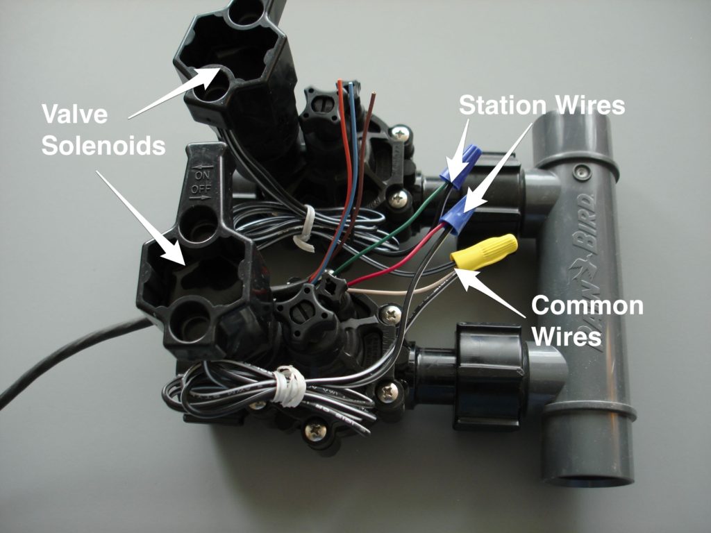
When the timer wire reaches the valve box, the white (common) wire is attached to one wire from each solenoid. It doesn’t matter which one. Then the other wire from each solenoid is attached to a station wire. In the example above, you can see that the white (common) wire is attached to a wire from each solenoid, and that the red wire and green wires are attached to the remaining two solenoid wires. If there were four valves in this example, one wire from each valve would be wired together to the white (common) wire for a total of 5 wires attached together, and one wire from each valve would be wired to a separate colored station wire.
In the above example if the red wire was attached to the timer at the station 1 terminal, that valve becomes station 1. If the green wire were attached to station 3, it would become station 3. Make sense?
I have seen sprinkler systems where the installation made a color change between the timer and the valves. Usually this occurred because there were multiple valve boxes and they didn’t wire color to color for some reason. In other systems I have worked on the installation contractor made a splice between the timer and the valve and the splice was buried. These types of installations are a nightmare to work on, because often times where the splice is made the wires will corrode and lose conductivity to the valves.
If at all possible when installing timer wire, make an entire run from the timer to the valves without an underground splice.